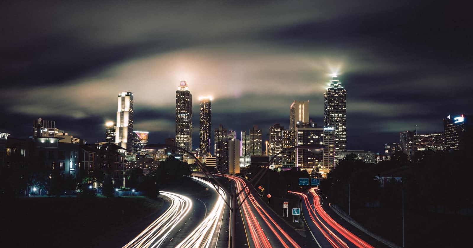
Photo by Adrian Schwarz on Unsplash
Crafting a DIY Intervalometer: My Journey from GoPro to DSLR Timelapses
Article Published: December 3, 2016
I've always been captivated by timelapses. Not only do I enjoy creating them, but I also appreciate the works of other enthusiasts.
My Timelapse Creation
The timelapse showcased above was captured during an ultimate frisbee session. I utilized my GoPro for this, and the post-production was done using After Effects. However, I found the GoPro's quality lacking and would have preferred using my DSLR. Surprisingly, many DSLRs lack a built-in intervalometer. When I looked for one online, they were exorbitantly priced. This led me to explore the possibility of crafting one using an Arduino.
With the resources available to me, I discovered a method to trigger the camera using an Arduino paired with an IR LED. I stumbled upon a timing diagram online, taken from an oscilloscope connected to the IR LED of a Canon IR remote. This diagram, with its clear timings, was instrumental in helping me recreate the necessary signal.
Unfortunately, this project was undertaken at a time when I didn't fully grasp the significance of thorough documentation. However, I do have a video capturing the initial success:
Having achieved the initial step of triggering a camera with an Arduino, I then set my sights on developing an intervalometer. I managed to construct one in time for our university's open day, where I also showcased my smart home project. Here's a snippet of me demonstrating the prototype:
While the prototype was a success, it wasn't particularly user-friendly. It required a proper casing, and the circuitry needed to be transferred from a breadboard to a PCB. Before I could embark on this, I learned of a remote trigger method using a 2.5mm headphone jack. By connecting the shutter wire to the ground after plugging the jack into the DSLR's remote port, one could capture a photo. Another wire was designated for focusing. Armed with this knowledge, I refined my remote:
Despite the improvements, the design wasn't portable. During a holiday break, I seized the opportunity to design a PCB version of the remote, focusing solely on the 2.5mm jack control. This not only reduced power consumption but also simplified the coding process. The result was a portable remote:
This iteration featured an OLED screen and utilized two opto-isolators to manage the focus and shutter. I also added external switches for easier access. While this remote was highly functional, its exposed components made it fragile. I encountered occasional display issues due to loose wire connections, which I resolved by soldering them directly.
What I particularly cherished about this remote were its features like "bramplapse" and "Astrolapse", typically found in pricier models. Given that I already had most of the components, the overall cost was between $15 to $20.
I apologize for the scant documentation. I plan to revisit this project, ensuring comprehensive documentation this time. I aim to have the circuit printed professionally (I've previously collaborated with Seedstudio) and will make the design publicly accessible.
For those interested, here's the code I employed to produce the following timelapses. Ensure you have ffmpeg installed:
import os
import shutil

imagenumber = 0
pics_dir = 'myfootage'
new_dir = "timelapsefootage/"
outputname = 'timelapse.mp4'

os.system("mkdir timelapsefootage")

files = sorted([str(filename) for filename in os.listdir(pics_dir)])
for filename in files:
    newname = new_dir + str(imagenumber) + ".JPG"
    os.system(f"cp {pics_dir}/{filename} {newname}")
    imagenumber += 1

cmd = f'ffmpeg/ffmpeg -f image2 -i {new_dir}%d.JPG -r 25 -s 960x640 -vcodec libx264 {outputname}'
os.system(cmd)
shutil.rmtree('./timelapsefootage')
Ensure your images are placed in a directory named myfootage, located in the same directory as the script. This code ensures your images remain in sequence, a challenge I initially faced. It's compatible with Python 2.6.
I hope this proves beneficial to someone out there!
